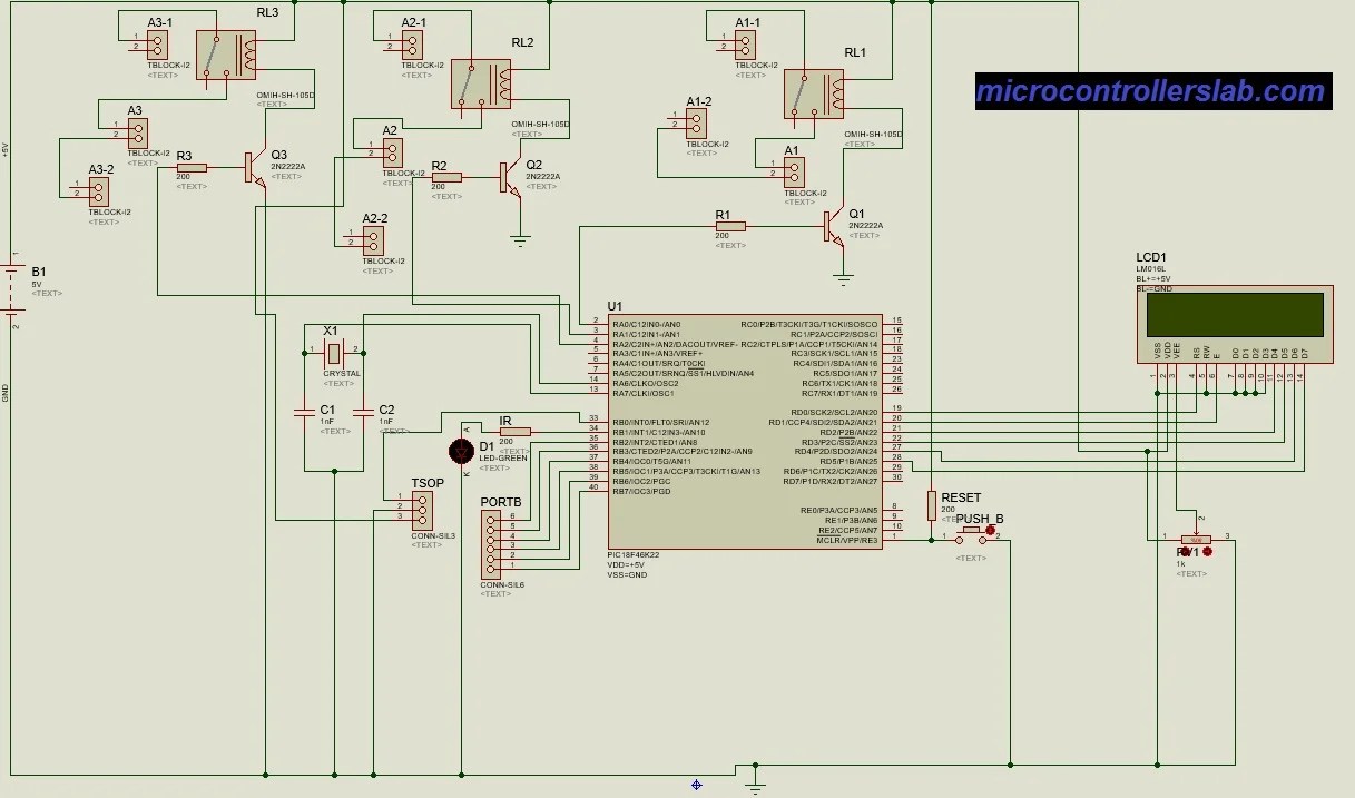
Schematic Diagram Of Tv Remote Control. This oscillation makes sure if the signal can be distinguished from other source by the receiver. Here is the schematic diagram of the circuit:
Tv remote controlled home automation system using pic microcontroller from microcontrollerslab.com
It is also effective when your children aren’t permitted to watch tv as a punishment. Putting the tv on standby and putting. Remote control light switch circuit circuito electronico.
The Transmitter Is Basically An Oscillator Circuit, And The Frequency Can Be Adjusted Using R1 Potentiometer (Or Trimmer Pot).
Tv remote control jammer circuit principle. The 10k potentiometer must be set to adjust the frequency to be matched with the remote control’s frequency to block. Circuit diagram of remote controlled switch project single load this is a schematic circuit diagram of a remote controlled switch for home appliances.
That Means The Ir Led Blinks At A Rate Of 32 Khz.
It is configured as a comparator. Simple on off remote control circuit diagram. A versatile remote controlled switch circuit with diagram and schematic that can control any appliance designed using ir remote sensor ic tsop 1738 and ne 555.
Putting The Tv On Standby And Putting.
Also here are more than 500 samsung tv schematics diagrams ! A simple remote tester circuit using just 2 transistors can be seen in the above figure. This is a good solution for a unique and so interesting idea to wireless switching system to control the home appliance.
Cpu Pic12F629 At 4Mhz Crystal For Tx/Rx, 3 Channel Output Relay, The Tx Use Sleep Mode For Saving Battery Power, Use Phillips Rc5 Protocol, Distance More Than 7 M, Easy Circuit To Build And Assembly And Small Amount Of Components.
Because this is too fast for a camera to pick, it picks up continuous turned on pulse. This circuit uses infra red leds that receive a current from transistor. First of all, the reason why i need to locate the schematic of a universal remote control was to understand in detail the circuitry on how the remote control works.the reason being i am currently trying to design some hardware which will.
Most Of The Tv Remotes Have 38Khz Operating Frequency.
Remote controlled light switch remote controlled light switch. A tv remote control signal jammer circuit diagram is shown above. For the sake of simplicity we have taken 3 select buttons, 1 each for tv, dvd and dth (you can choose any appliance depending on your requirement).